Showing posts with label Sensor. Show all posts

Saturday, June 6, 2015

Hand Gesture control RF Robot

Animatronic Arm / Hand Gesture control RF Robot

Abstract: In this project we are going to design an Animatronic Arm/Hand Gesture RF robot, It has two functions
1. RF based Animatronic Arm/Hand Gesture 
2. RF controlled mobile Robot

The system block diagram is shown in the below figure. It contains
a). Flex Sensors 
b). Opamps
c). ATmega16-A board
d). 433MHz RF transceiver s
e). 8052 controller
f). DC Motors and servo motors
g). HT12D and HT12E 
h). Motor driver L293D

Working of Mobile Robot: 
At the transmission section we have HT12E with 4 push buttons and a 433MHz transmitter as shown in fig.1, 4 buttons are used for forward,backward, left and right controls.

At the receiver section RF receiver will receive the transmitted data and HT12D decodes the received data and sends 4-data bits to the motor driver L293D as shown in fig.2.

Block Diagram
Fig.1 Transmitter Circuit for Robot Movement
Fig.2 Receiver Circuit for DC motor Controlling
Working of Animatronic Arm:
Flex sensors are a kind of variable resistors, who's resistance varies with flexing. This application is used in animatronic arm. The basic circuit of flex sensor is shown in the below circuit, it is connected as a potential divider circuit and the output is connected to a buffer. The voltage variation can be calculated by 'Vout' equation.


Here we used two flex sensors for two fingers. Output of the buffers are given to the analog pins of ATmega16-A board. Inside the controller analog data is converted to digital form and based on the two output values 4-bit data is sent to the I/O ports. 4-bit output is then given to the HT12E encoder and it transmits the data as shown in fig.3 and 4

Fig.3 Flex Sensor circuit

Fig.4 ATmega16-A circuit for data processing
At the receiver side the received is then decoded and given to the 8052 controller. The code is written such that the animatronic arm imitates your fingers based on the flex sensor voltage values.  The pulse width of the servo motors is changed according to the received data. The total pulse width is 20ms. for a 1 ms ON time it will be at 0 degrees and for 1.5 ms ON time shaft position will be at 90 degrees and for 2 ms ON time at 180 degrees as shown in the below fig.5 and 6

Fig.5  Receiver Circuit interfaced with 8051
Fig.6 servo motor interface with 8051
Working Video:

Resources:

1. ATmega16-A Transmitter CODE Download the code here
2. 8052 Receiver CODE Download the code here

NOTE: 
1. Since we used two pairs of RF transceivers we used different address at HT12D/E
2. We have designed it for only two fingers and a basic movement.
    For 5 fingers and much more degree of freedom use 5 flex sensors and Zigbee module 

Saturday, December 21, 2013

Engine Running Detector, Load Switch


While the concept is simple, there are numerous problems involved as follows:
  1. Voltage must be sensed as close to the battery as possible, and voltage sense wiring must be separate from power wiring—hence the requirement for the Kelvin connection. This is why I wrote the recent article: What is a Kelvin Connection?
  2. Since this circuit is connected directly to the battery, circuit protection is absolutely essential. This is why I wrote the recent article: Low Voltage & Automotive Circuit Protection.
  3. Voltage threshold must be accurate—requires stable voltage reference.
  4. Circuit must have hysteresis for positive switching.
  5. Load switch must have substantial delay to prevent unintended or nuisance switching.
  6. Quiescent current must be low to prevent battery discharge.
  7. Charging system must function correctly—alternator must float charge the battery as well as power all connected accessories when engine is at idle speed.
  8. Due to variations in battery charging voltage in different systems and a relatively narrow voltage threshold window, there is no one size fits all voltage setting. As a result, the threshold must be adjustable.
Due to these complexities, this circuit is not recommended for the novice. However, if installed using proper circuit protection & wiring practices, the only failure mode is unintended battery discharge should it not automatically disconnect the load.
Schematic
12V Load Switch
Source or native rfflow file
Gathering components prior to assembly
components
Perf board prototype

Circuit overview
U1 is the voltage reference—its output is a stable, low impedance voltage source. R3, 4, & 5 form an adjustable battery voltage divider for setting threshold voltage. U2A is a voltage comparator (popular LM339 quad comparator). R6 & R7 provide positive feedback—R6 sets the hysteresis. R8, 10 & 14 are pull-up resistors for the open collector outputs. D3 is the threshold indicator LED. U2B is simply an inverter. R11 & C2 make up a 20sec delay circuit. U2D is the MOSFET driver. R13 & R12 provide positive feedback for positive switching. D5 discharges C2 when power is removed. R15 & D2 protect the MOSFET gate from over-voltage. D6 is the output ON indicator LED.
Circuit operation
After engine is started and battery reaches float charge voltage, the circuit starts timing. After about 20sec, the load switch Q2 turns on thus powering the load—Q2 is a high-side switch. When engine is stopped, the battery voltage drops below the float charge voltage. Then the timer starts to time out again—after approx. 20sec, the load switch turns off.
MOSFET P-Channel power device
Q1 has been selected to power up to a 15A load without dissipating excessive heat. An 80A device (P80PF55) is specified and it requires a heatsink because the power dissipation = 4W @ 15A. For 10A or less, a lower current device such as the 27A FQP27P06 may be used. Or, this device may simply power the coil of a relay or contactor.
Setup on bench
Take and log voltage measurements on vehicle.
Calculate average voltage.
Set bench power supply to equal average voltage and connect to unit.
Adjust R4 to point where threshold LED (D3) just comes on.
Voltage measurements from my two old cars
EngineStoppedRunningAverage
Chrysler13.09V14.49V13.79V
Toyota12.28V14.58V13.43V
Installation—first read and apply the following information
http://www.electroschematics.com/6970/low-voltage-automotive-circuit-protection/ 
http://www.electroschematics.com/6959/kelvin-connection/
Set up on vehicle
When engine is at idle speed and battery is at float charge voltage, rotate R4 clockwise until LED D3 lights—then increase setting slightly.
Testing
Determine that load switches on properly after 20sec time delay. Then stop engine and see if threshold LED D3 extinguishes (may take a few seconds), and load is subsequently disconnected after an additional 20sec time delay. Restart engine and observe that all now functions automatically. Note that this delay is inconsistent if engine is started, stopped and restarted quickly.
For the future
AC mains load switch
Undocumented words and idioms (for our ESL friends)
perf board — perforated fiberglass epoxy sheet
one size fits all — universal size clothing (largest size)

Friday, December 20, 2013

Quadrocopters for beginners

Quadrocopters for beginners

Intro to quadrocopters

Quadrocopters, also known and quadrotors, are one of the most interesting little flying machines ever imagined; yet there's a load of disperse and almost undecipherable amount of information that comes from hobbyists' and builder's gut feeling on what seems to be the right thing to do.

This is my attempt at bringing all that information together in a simple to understand version for beginners to get designing their own quadrotors.

How they work

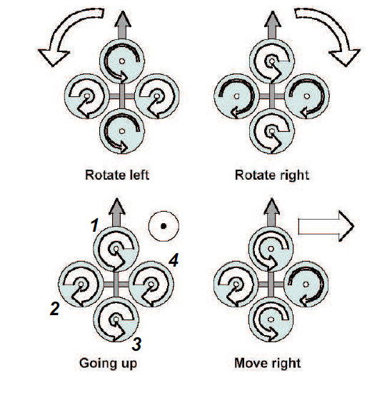
Quadrotor diagram showing forces and torques

The concept is a flying machine with four motors aligned in a square; two on opposite sides of the square rotate in one direction and the other two rotate in the opposite direction.

This four rotor helicopter gives us some interesting properties:

1.- each motor lifts only a quarter of the weight of the heli, so we can potentially use less powerful motors

2.- the rotation or torque of the first pair of motors is canceled by the rotation of the second pair that goes in the opposite direction. Let me explain how this works:

On a regular helicopter, you have one big rotor to provide the lifting power and a little tail rotor; this one counteracts the rotation that the main big rotor would otherwise pass on to the structure of the helicopter (making it rotate almost as fast as the propeller)

On a quadrotor, if all motors turned on the same direction the thing would rotate same as a regular heli without tail rotor; the clever thing is that since one pair create a torque or rotation on one direction, the motors turning on the opposite direction create a torque also but on the opposite direction. These torques tend to cancel out and the quadrocopter stays facing the same direction without any rolling around.
Quadrotor control; arrow thickness denotes power

3.- control becomes a matter of which motor gets more power and which one gets less.

Yaw (where the thing is "facing"; using your head, yaw is when turning left and right) is controlled by turning up the speed of the regular rotating motors and taking away power from the counter rotating; by taking away the same amount that you put in on the regular rotors produces no extra lift (it won't go higher) but since the counter torque is now less, the quadrotor rotates as explained earlier.

Roll (how tilted to the side it is while still facing the same direction; using your head, roll is turning it so that your chin is parallel to the ground) is controlled by increasing speed on one motor and lowering on the opposite one.

Pitch (how tilted it is; using your head is moving it up and down, similar to nodding) is controlled the same way as roll, but using the second set of motors. This may be kinda confusing, but roll and pitch are determined from where the "front" of the thing is, and in a quadrotor they are basically interchangeable; but do take note that you have to decide which way is front and be consistent or your control may go out of control.

These three can be controlled at the same time to give all the range of motion you could ever need from a flying thing


Now, building and flying a quadrotor from a remote control is simple and fun and stuff, but people noting the inherently stable flight (in theory with equal speed of the motors the thing keeps itself level) and ease of control (only three functions and they are all basically take speed from one and put in the other), people love to make them autonomous (flies itself) and semi-autonomous (at least keeps itself level by responding to disturbances and error).

Common sensors (Gyro, Accelerometer, Sonar/Rangefinder)

A gyroscope is a device that tells you the difference in angle from a reference one: this is useful in keeping the quadrocopter level so it won't fall or go sideways when we don't want it to.
Micro ElectroMechanic Mechanism (MEMS) gyroscope
as found in Integrated Circuit (IC) sensors

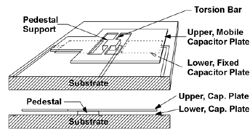
The accelerometer tells us which way the quadrotor is accelerating. This is useful because we can get an idea of how much the thing has moved by looking at acceleration over time (position is mathematically represented as the double integral of acceleration) so that we can move it back and keep it hovering on a steady position.

MEMS Accelerometer based on capacitive effects


A sonar is used to determine the distance from the sensor to an object. This helps in object detection an avoidance and is mostly used in fully autonomous quadcopters.


All these sensors are connected to a microcontroller or other control circuitry to make the decision as to how to control the motors (and therefore the quadrotor itself) according to plan.

Depending on how autonomous you want it to be, one or more of these sensors are used in combination; sometimes more sensors are used or more processing is done on the signals to get more information about the environment: creating maps, computer vision and navigation systems.

The flight mechanics of the quadrocopter, as explained in the how it works section, are not that difficult, but a "design" limitation is the choosing of motor/propeller.

Choosing a motor/propeller combo (prop size and RPM: lift vs torque)

There's something about aerodynamics that is just way too complex for beginners to get a working understanding of in a few words, all the fluxes and stuff makes it hard enough that even designers of commercial propellers bunch a lot of things into "constants" or "factors" that they arrive at experimentally.

But generally, the importan stuff depends largely on two things: the effective area of the propeller and RPM (revolutions per minute).

Revolutions per minute are largely dependent on the motor, in fact, it is one of the parameters used in their marketing; usually expressed as Kv, RPM per volt applied.

The propeller is marketed in terms of diameter x "pitch". the higher diameter means higher area; higher pitch also means higher effective area because more of the propeller is pushing air to create lift.
Various propeller sizes and pitches

In choosing a motor/propeller combination, you have to figure out what you actually need or want out of the quadrotor:

A higher RPM of the propeller will give you more speed and maneuverability, but it is limited in the amount of weight it will be able to lift for any given power. Also, the power drawn (and torque required) by the motor increases as the effective area of the propeller increases, so a bigger diameter or higher pitch one will draw more power at the same RPM, but will also produce much more lift (meaning it will be able to actually lift more weight). [Torque is like the rotating power of the motor]

A slower rotating propeller is used when you have a motor that manages less revolutions but can provide more torque. In this case using a longer or higher pitched propeller (which uses more torque to move more air in order to create lift) will give you a similar lift to a higher rotating one of less length/pitch.

The choice depends on both motor availability and weight requirements.

Motor technologies: Brushed vs brushless motors

There's a debate regarding the use of brushed or brushed motor. First, a brief explanation of both:
Brushed motor

A brushed motor is your regular $1 toy car motor. They are called brushed because of the way the motor works: the direction of current in the rotating part (rotor) is changed using a mechanical switching mechanism, a pair of moving contacts called brushes disconnect from one side and connect to the other with every half rotation. This is done so the electric current keeps the rotor energized in such a way so as to keep being attracted to the permanent magnets, thus keeping it rolling.
Brushless motor inside view

A brushless motor is one where the commutation mechanism is outside the motor itself, most often electronic. The thing with brushless motors is that there are no moving parts in the electrical path of current, so it generates less electromagnetic noise as there are no sparks (which happens in brushed motors when the brushes disconnect and connect on the other side).

The debate goes about how brushless motors, with its fewer moving or parts, requires less maintenance and has higher performance for size and that brushed motors are "old", obsolete technology.

For the most part, the actual gains in performance come from the thermal characteristics of the motor: given the same power, a brushless motor will probably be smaller due to the fact that the heat dissipates through the mounting (remember, the windings are stationary and attached to the motor frame), a bigger motor. This means that for the same size motor, you can push much more current through a brushless to get more power.

Now here comes the big "but": since they have been around the longest, brushed motors have become very cheap to manufacture, which means prices are very low. Also, since the commutation in brushless motors is external, there's an added cost of buying and/or building the Electronic Speed Controller (ESC), which could cost as much or even more than the motor itself (which even on the lower range are more expensive than brushed motors), also with the increased complexity that comes with more components to deal with.

Brushed motors use a relatively simple speed control technique known as Pulse Width Modulation (PWM) that controls the effective power that the motor gets by quickly switching the power on and off.

So as you can see, there's a lot to dig into when working in quadrocopters. Next up, assembling our own quadrotor and the whole design process.

Water triggered alarm system with 555 timer

Water triggered alarm system with 555 timer


You can use this circuit for you water tank.then you can know before over flowing your tank.on the other hand you can use this circuit as a rain detector then you can know before rain comes.so I suppose this would be a so useful circuit for you


Thursday, December 12, 2013

Fingerprint Based Security System Using R303 Module

Fingerprint Based Security System Using R303 Module


Here i am presenting you a Fingerprint based security system using r303a module. By using this you can secure a room, office, lockers or any private areas. The basic principle used in this project is Biometric Authentication, it refers to the identification of humans by their physical or behavioural characteristics. The physical biometric authentication involves


  • FINGERPRINT
  • VOICE
  • FACE
  • IRIS


Here we are using fingerprint as the identification factor, for that a fingerprint module R303 is used. it is a low cost, high performance, easily available one and can be able to store upto 120 fingerprint images in its memory. We can also interface it with a computer by means of max232 level converter. The fingerprint module R303 can be divided into two sections


Fingerprint Scanning section: This involves, the scanning of finger and generating a template corresponding to the alignment of ridges and valleys present in a fingerprint image. this template is then converted to a character file and will stored in its database.


Fingerprint Searching Section: This includes the identification of a fingerprint by searching each and every template that is stored in its database. The fingerprint that is to be identified will compare all the templates and generate a positive or negative acknowledge.


CIRCUIT DIAGRAM

Fingerprint security system circuit


The microcontroller AT89S52 interacts with the module. We can add, delete or identify the fingerprint as required with the switches provided. This can be connected to any device through relay, which needs to be controlled. Microcontroller will generate the necessary HEX codes for the proper operation of fingerprint module and it is also used to Display Messages on LCD.


To ADD your Fingerprint on the system, just show your thumb or forefinger to the module twice as prompts while pressing the ADD button in the circuit.


The buzzer is used to generate alarm, if the fingerprint identified doesnot matches with the enrolled one and if it matches the relay will be activated.


PROTECTION FOR YOUR ELECTRICAL APPLIANCES

PROTECTION FOR YOUR ELECTRICAL APPLIANCES

Hasifnoor_Attasheri


Here is a very low-cost circuit to save your electrically operated appliances, such as TV, tape recorder, refrigerator, and other instruments during sudden tripping and resumption of mains supply. Appliances like refrigerators and air-conditioners are more prone to damage due to such conditions.


The simple circuit given here switches off the mains supply to the load as soon as the power trips. The supply can be resumed only by manual intervention. Thus, the supply may be switched on only after it has stabilised.

The circuit comprises a step-down transformer followed by a full-wave rectifier and smoothing capacitor C1 which acts as a supply source for relay RL1. Initially, when the circuit is switched on, the power supply path to the stepdown transformer X1 as well as the load is incomplete, as the relay is in de-energised state. To energise the relay, press switch S1 for a short duration. This completes the path for the supply to transformer X1 as also the load via closed contacts of switch S1. Meanwhile, the supply to relay becomes available and it gets energised to provide a parallel path for the supply to the transformer as well as the load.

If there is any interruption in the power supply, the supply to the transformer is not available and the relay de-energises. Thus, once the supply is interrupted even for a brief period, the relay is de-energised and you have to press switch S1 momentarily (when the supply resumes) to make it available to the load.

Very-short-duration (say, 1 to 5 milliseconds) interruptions or fluctuations will  not affect the circuit because of presence of largevalue capacitor which has to discharge via therelay coil. Thus the circuit provides suitable safety against erratic power supply conditions.

LONG RANGE FM TRANSMITTER

LONG  RANGE FM TRANSMITTER  


Hasifnoor_Attasheri


Several circuits for constructing FM transmitters have been published in EFY. The power output of most of these circuits were very low because no power amplifier stages were incorporated. 

The transmitter circuit described here has an extra RF power amplifier stage, after the oscillator stage, to raise the power output to 200-250 milliwatts. With a good matching 50-ohm ground—plane antenna or multi-element Yagi antenna, this transmitter can provide reasonably good signal strength up to a distance of about 2 kilometres.


The circuit built around transistor T1 (BF494) is a basic low-power variable- frequency VHF oscillator. A varicap diode circuit is included to change the frequency of the transmitter and to provide frequency modulation by audio signals. The output of the oscillator is about 50 milliwatts. Transistor T2 (2N3866) forms a VHF-class A power amplifier. It boosts the oscillator signals’ power four to five times. Thus, 200-250 milliwatts of power is generated at the collector of transistor T2.

For better results, assemble the circuit on a good-quality glass epoxy board and house the transmitter inside an aluminium case. Shield the oscillator stage using an aluminium sheet Coil winding details are given below:
L1 – 4 turns of 20 SWG wire close wound over 8mm diameter plastic former.

L2 – 2 turns of 24 SWG wire near top end of L1.

(Note: No core (i.e. air core) is used for the above coils)

L3 – 7 turns of 24 SWG wire close wound with 3mm diameter air core.

L4 – 7 turns of 24 SWG wire-wound on a ferrite bead (as choke)

Potentiometer VR1 is used to set the centre frequency whereas potentiometer VR2 is used for power control. For hum free operation, operate the transmitter on a 12V rechargeable battery pack of 10 x 1.2-volt Ni-Cd cells. Transistor T2 must be mounted on a heat sink. Do not switch on the transmitter without a matching antenna. Adjust both trimmers (VC1 and VC2) for maximum transmission power. Adjust potentiometer VR1 to set the centre frequency near 100 MHz.

This transmitter should only be used for educational purposes. Regular transmission using such a transmitter without a licence is illegal in India.

AUTOMATIC TEMPERATURE CONTROLLED FAN

AUTOMATIC TEMPERATURE CONTROLLED FAN

Hasifnoor_Attasheri


Here is a circuit through which the speed of a fan can be linearly controlled automatically, depending on the room temperature. The circuit is highly efficient as it uses thyristors for power control. Alternatively, the same circuit can be used for automatic temperature controlled AC power control.


In this circuit, the temperature sensor used is an NTC thermistor, i.e. one having a negative temperature coefficient. The value of thermistor resistance at 25°C is about 1 kilo-ohm.

Op-amp A1 essentially works as I to V (current-to-voltage) converter and converts temperature variations into voltage variations. To amplify the change in voltage due to change in temperature, instrumentation amplifier formed by op-amps A2, A3 and A4 is used. Resistor R2 and zener diode D1 combination is used for generating reference voltage as we want to amplify only change in voltage due to the change in temperature.

Op-amp μA741 (IC2) works as a comparator. One input to the comparator is the output from the instrumentation amplifier while the other input is the stepped down, rectified and suitably attenuated sample of AC voltage. This is a negative going pulsating DC voltage. It will be observed that with increase in temperature, pin 2 of IC2 goes more and more negative and hence the width of the positive going output pulses (at pin 6) increases linearly with the temperature. Thus IC2 functions as a pulse width modulator in this circuit. The output from the comparator is coupled to an optocoupler, which in turn controls the AC power delivered to fan (load).

The circuit has a high sensitivity and the output RMS voltage (across load) can be varied from 120V to 230V (for a temp. range of 22°C to 36°C), and hence wide variations in speed are available. Also note that speed varies linearly and not in steps. Besides, since an optocoupler is used, the control circuit is fully isolated from power circuit, thus providing added safety. Note that for any given temperature the speed of fan (i.e. voltage across load) can be adjusted to a desired value by adjusting potmeters VR1 and VR2 appropriately.

Potmeter VR1 should he initially kept in its mid position to realise a gain of approximately 40 from the instrumentation amplifier. It may be subsequently trimmed slightly to obtain linear variation of the fan speed.

CLAP SWITCH

CLAP SWITCH    

Hasifnoor_Attasheri


Here’s a clap switch free from false triggering. To turn on/off any appliance, you just have to clap twice. The circuit changes its output state only when you clap twice within the set time period. Here, you’ve to clap within 3 seconds.

The clap sound sensed by condenser microphone is amplified by transistor T1. The amplified signal provides negative pulse to pin 2 of IC1 and IC2, triggering both the ICs. IC1, commonly used as a timer, is wired here as a monostable multivibrator. Trigging of IC1 causes pin 3 to go high and it remains high for a certain time period C3. This ‘on’ time (T) of IC1 can be calculated using the following relationship:

T=1.1R7.C3 seconds
where R7 is in ohms and C3 in microfarads. On first clap, output pin 3 of IC1 goes high and remains in this standby position for the preset time. Also, LED1 glows for this period The output of IC1 provides supply voltage to IC2 at its pins 8 and 4. Now IC2 is ready to receive the triggering signal. Resistor R10 and capacitor C7 connected to pin 4 of IC2 prevent false triggering when IC1 provides the supply voltage to IC2 at first clap.

On second clap, a negative pulse triggers IC2 and its output pin 3 goes high for a time period depending on R9 and C5. This provides a positive pulse at clock pin 14 of decade counter IC 4017 (IC3). Decade counter IC3 is wired here as a bistable.


Each pulse applied at clock pin 14 changes the output state at pin 2 (Q1) of IC3 because Q2 is connected to reset pin 15. The high output at pin 2 drives transistor T2 and also energises relay RL1. LED2 indicates activation of relay RL1 and on/off status of the appliance. A free-wheeling diode (D1) prevents damage of T2 when relay de-energises. 


LASER COMMUNICATION SYSTEM

LASER COMMUNICATION SYSTEM 

Hasifnoor_Atatsheri


This laser communication system transmits sound or music signals through a laser beam. The intensity of the laser beam changes with the amplitude of the sound signal. The variation in the intensity of the laser beam is converted into a variation in the voltage level by using a calculator's solar panel. The voltage variation on the solar panel is amplified by a low-voltage audio power amplifier LM386 and reproduced by a speaker. The maximum output of audio amplifier LM386 is 1 watt, while its voltage gain is 20 to 200. 

he circuit consists of a transmitter and a receiver. Both the transmitter and the receiver are built around IC LM386, powered by a 9V battery.

Fig. 1 shows the transmitter circuit. Here a laser diode (LD1) with maximum operating voltage of around 2.6V DC and maximum operating current of 45 mA is used to transmit the audio signal. The voltage divider network formed by R2, R3 and VR3 keeps the voltage as well as the current for the laser diode in the safe region. 


Fig. 1: Transmitter circuit 

In place of the laser diode, you can also use a laser pointer. Remove the battery from the laser pointer. Extend two wires from terminals of LD1 and connect them to the battery terminals of laser pointer. The spring inside the laser pointer is the negative terminal. The output power of the laser pointer is 5 mW. Take care while working with laser, as direct exposure to the laser beam can be hazardous to your eyes. Point the laser beam to the solar panel.

Potmeter VR1 (10-kilo-ohm) is used to change the level of the input audio signal. The audio input (Vin) is taken from the preamplifier output of the music system (CD player, DVD player, etc). Capacitor C2 and preset VR2 are used to vary the gain of the LM386.

Fig. 2 shows the receiver circuit. The audio signal transmitted by the laser diode (LD1) is received by the calculator's solar panel and amplified by IC2. The gain of the amplifier is fixed by capacitor C7. Preset VR4 is used to change the signal level from the solar panel. This signal is fed to input pin 3 of IC2 through coupling capacitor C5 so that the DC value from the solar panel can be eliminated. The amplified output from IC2 is fed to the speaker, which plays the music from the CD player connected at the input (Vin) of IC1. 


Fig. 2: Receiver circuit 

Assemble the transmitter and receiver circuits on separate PCBs and enclose in suitable cabinets. In the transmitter cabinet, fix two terminals for connecting the audio signal. Fix switch S1 on the front panel and the laser diode (LD1 or laser pointer) to the rear side of the cabinet. Keep the 9V battery inside the cabinet.

In the receiver cabinet, fix the calculator's solar panel to the rear side such that the transmitted beam directly falls on it. Fix switch S2 on the front panel and the speaker to the rear side. Keep the 9V battery inside the cabinet. Refer Figs 3 and 4 for the laser pointer and calculator's solar panel.

After assembling both the circuits, orient the laser diode (or laser pointer) such that the transmitted laser beam directly falls on the solar panel. Use shielded wires for connecting to audio input and solar panel to reduce noise pickup.


Fig. 3: Laser pointer 


Fig. 3: Solar  Panel

Remote Control for Toy Car

Remote Control for Toy Car 

Hasifnoor_Attasheri


Make any battery-operated toy car remote-controlled using this circuit. The circuit, consisting of an infrared transmitter-receiver pair, uses IR beam transmission to switch the toy car 'on' or 'off '. To operate the toy car, you need to hold the transmitter in your hand, keeping it pointed at the toy car which has the receiver fitted inside, and simply press a switch provided on the transmitter. 

The transmitter works off 9V DC, while the receiver needs 6V DC. Fig. 1 shows the transmitter circuit. It is built around two BC558 transistors (T1 and T2), ,three BC548 transistors (T3, T4 and T5), IR LED1 and a few discrete components. 


Fig. 1: Transmitter circuit 

Fig. 2 shows the receiver circuit. It is built around IR receiver module TSOP1738, two BC548 transistors (T6 and T7) and a few discrete components. In the transmitter circuit, there are two astable multivibrators. The first, built around transistors T1 and T2, produces a frequency of about 1.2 kHz. The second, built around transistors T3 and T4, produces about 38 kHz. IR LED1 is used to transmit the 38kHz frequency. 


Fig. 2: Receiver circuit 

In the receiver circuit, TSOP1738 receives the IR signal transmitted by IR LED1 of the transmitter circuit. The output of TSOP1738 is fed to transistor T6 via diode D1. The amplified signal is further given to relay-driver transistor T7. Relay RL1 energises to control the toy car.

Working of the circuit is simple. Initially, when no IR beam is falling on sensor TSOP1738, the relay remains de-energised and the toy car doesn't move. When switch S1 is pressed, the IR beam falls on TSOP1738 and its output goes low. Transistor T6 cuts off and transistor T7 conducts to energise relay RL1 and move the toy car. 

Assemble both the circuits on separate PCBs. Enclose the transmitter PCB in a suitable cabinet, with IR LED1 affixed on the front side and switch S1 on the top of the cabinet. Keep the 9V battery inside the cabinet. 

Enclose the receiver PCB inside the toy car, with TSOP1738 fitted such that the transmitted IR beam directly falls on it. Fix switch S2 on the body of the car and the relay inside the car. Use a 6V battery to operate the toy car receiver unit.

Anti-Petrol Theft Alarm

Anti-Petrol Theft Alarm 

Hasifnoor_Attasheri


P
etrol/diesel theft of parked vehicles is quite common. Presented here is an audio-visual anti-petrol theft alarm circuit that can help prevent this crime. The circuit consists of transmitter and receiver sections. The transmitter has to be mounted in the vehicle near the petrol tap, and the receiver in the common room of your house. When someone comes near the petrol tap, you get an audio-visual indication in your room.

Fig. 1: Transmitter section


The transmitter section (shown in Fig. 1) is built around an infrared LED (IR LED1), photodiode (PD1), comparator IC 741 (IC1), phase-locked loop IC 567 (IC2), 433MHz transmitter (TX1) and a few discrete components. Power supply to the circuit is given by the vehicle’s 12V battery through switch S1.

When someone comes near IR LED1, the IR signal reflected off the subject is detected by photo-diode PD1. A voltage difference appears at inverting pin 2 of IC1 and its pin 6 goes high. As a result, npn transistor T1 conducts and enables the PLL 567 to transmit a prefix frequency via transmitter TX1. LED1 glows when a signal is transmitted.

Fig. 2: Receiver section

The receiver section (shown in Fig. 2) is built around an infrared receiver module (RX1), PLL 567 (IC3), EFY-KnS 8051 development board along with some discrete components. It operates off a 9V-12V battery. Alternatively, you can use a 12V adaptor. Switch S2 is used to power the circuit.

Transmitted frequency from the transmitter is received by the RF receiver module (RX1) and decoded by PLL567 (IC3). The output of IC3 is fed to input port pin P1.1 of EFY-KnS 8051 development board. The output port pin P2.2 is connected to transistor T2 to drive the buzzer and LED2. The EFY-KnS 8051 development board is used for speedy development and is available from EFY associates Kits’n’Spares (KnS).

The software is written in ‘C’ language on KEIL version 4.0 demo platform. Programming of the development board is simple and mentioned in the manual provided with the development board.
Assemble the transmitter and receiver circuits on two separate general-purpose PCBs. Connect the battery of the vehicle to the transmitter circuit. Fit IR LED1 and photo-diode PD1 of the transmitter such that if someone comes near the petrol tap, a signal can be transmitted through TX1. It would be better if you use a small 10mm wire as an antenna.

Mount switch S2 on the front side of the receiver unit along with LED2 and buzzer. Install the receiver PCB at your residence. When the receiver module receives a signal from the transmitter, LED2 will glow and at the same time buzzer PZ1 will sound.

Click here to view/download the source code of this circuit.