Showing posts with label Security. Show all posts

Saturday, December 21, 2013

Electronic Vehicle Immobilizer

Electronic Vehicle Immobilizer

Description

This simple vehicle immobilizer circuit is cheap, easy to make, install and operate . It’s also very discreet.
Thoroughly field tested, it’s robust and weather resistant design can prevent vehicle theft even if the thief has the keys!
In it’s most common application, it prevents the engine from turning over until the vehicles ‘G-Spot‘ is touched at the same time the key is turned to the ‘Start’ position, and the operator is earthed!
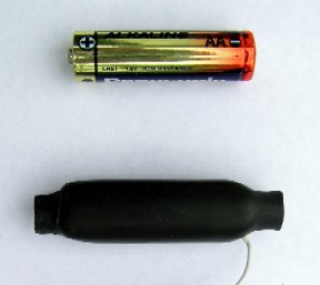
Here’s a completed G-Spot beside an AA battery:
Animated Schematic and Circuit Description
I know, it’s a little bit ‘fancy’:

Turning the vehicles key supplys power (red).
The SCR prevents operation of the load until the voltage on the base of the PNP transistor is lowered by the earthed owner contacting the G-Spot (green),
This turns the transistor on and current then flows through the collector circuit and 220 ohm resistor (orange), triggering the gate of the SCR.
Once triggered, the SCR allows power to flow to load (green) and remains on until power is isolated.

Parts and Materials

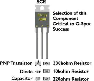
These are all the electronic components required ~ the diode is not essential:
These are all the mechanical components:
You’ll also need a small amount of:
Solder, cleaner, tape, lacquer, fiberglass resin and hardener.

Assembly and Basic Installation Instructions

There’s a few steps involved in these processes and they’re available here ~http://home.clear.net.nz/pages/dandavies/index.htm
There’s also more technical information and some history there too.
An alternative version showing the construction of a similar product which uses leaded components instead of surface-mount ones – no vero-board required can be watched on this YouTube video: http://www.youtube.com/watch?feature=player_embedded&v=FFb5_mKfnR8

Friday, December 13, 2013

Home Security Robot to prevent theft

Home Security Robot to prevent theft


SPECIFICATIONS
Title of the project                  :           Home Security Robot to prevent theft

Domain                                    :           Embedded Systems Design and Robotics

Software                                  :           Assembly, Proload

Microcontroller                      :           89S52 CISC Micro Controller

Power Supply                          :           +5V, +12V 500mA Regulated Power Supply

Display                                     :           a) LCD                         HD44780 16-character, 2-line (16X2)

                                                            b) LED              5mm

Crystal                                     :           11.0592MHz

Sensors                                    :           LDR/ PIEZO/TACTILE/ TEMPERATURE

Applications                            :           Homes, offices, shops, military, go downs, Farm house etc


ABSTRACT

Problem:         Many people are worried regarding the safety of their home/ office when they are away. 

Solution:          We have developed a small mobile robot that can guard the home when the owner is away from home. The robot has several on board sensors to detect home safety. Whenever it detects breach of safety, it sounds an alarm to draw the attention of the neighbors.

Implementation:         The robot has   a fire senor to detect fire, detects window break using piezo sensor element, also detects Door break using wire break sensor. A buzzer based alarm is triggered when the situation is abnormal. The robot keeps moving in the room when it is activated. It has bump sensor to detect wall in front of it.
The project is equipped to display various parameters using Liquid crystal display. The display consumes low power and operates with battery power also.

This project uses regulated 5V, 500mA power supply. 7805 three terminal voltage regulator is used for voltage regulation. Bridge type full wave rectifier is used to rectify the ac out put of secondary of 230/12V step down transformer.

Advantages:
  • Low cost implementation, Improves house safety, Digital indication of sensors,
  • Reliable sensors, Small size, Low Power consumption
Scopes for Advancements:
  • Remote control the robot from any where in the world
  • Cell mounted on the robot can provide visual information also
Target customers/Applications:
Homes, Offices, Shops, Military, go downs, Farm house etc

BLOCK DIAGRAM


Keep Visiting for more Updates
Thanks n regards,
- See more at: http://www.examsadda.com/2012/05/home-security-robot-to-prevent-theft.html#sthash.ZB7kvK2N.dpuf

Thursday, December 12, 2013

Fingerprint Based Security System Using R303 Module

Fingerprint Based Security System Using R303 Module


Here i am presenting you a Fingerprint based security system using r303a module. By using this you can secure a room, office, lockers or any private areas. The basic principle used in this project is Biometric Authentication, it refers to the identification of humans by their physical or behavioural characteristics. The physical biometric authentication involves


  • FINGERPRINT
  • VOICE
  • FACE
  • IRIS


Here we are using fingerprint as the identification factor, for that a fingerprint module R303 is used. it is a low cost, high performance, easily available one and can be able to store upto 120 fingerprint images in its memory. We can also interface it with a computer by means of max232 level converter. The fingerprint module R303 can be divided into two sections


Fingerprint Scanning section: This involves, the scanning of finger and generating a template corresponding to the alignment of ridges and valleys present in a fingerprint image. this template is then converted to a character file and will stored in its database.


Fingerprint Searching Section: This includes the identification of a fingerprint by searching each and every template that is stored in its database. The fingerprint that is to be identified will compare all the templates and generate a positive or negative acknowledge.


CIRCUIT DIAGRAM

Fingerprint security system circuit


The microcontroller AT89S52 interacts with the module. We can add, delete or identify the fingerprint as required with the switches provided. This can be connected to any device through relay, which needs to be controlled. Microcontroller will generate the necessary HEX codes for the proper operation of fingerprint module and it is also used to Display Messages on LCD.


To ADD your Fingerprint on the system, just show your thumb or forefinger to the module twice as prompts while pressing the ADD button in the circuit.


The buzzer is used to generate alarm, if the fingerprint identified doesnot matches with the enrolled one and if it matches the relay will be activated.


PROTECTION FOR YOUR ELECTRICAL APPLIANCES

PROTECTION FOR YOUR ELECTRICAL APPLIANCES

Hasifnoor_Attasheri


Here is a very low-cost circuit to save your electrically operated appliances, such as TV, tape recorder, refrigerator, and other instruments during sudden tripping and resumption of mains supply. Appliances like refrigerators and air-conditioners are more prone to damage due to such conditions.


The simple circuit given here switches off the mains supply to the load as soon as the power trips. The supply can be resumed only by manual intervention. Thus, the supply may be switched on only after it has stabilised.

The circuit comprises a step-down transformer followed by a full-wave rectifier and smoothing capacitor C1 which acts as a supply source for relay RL1. Initially, when the circuit is switched on, the power supply path to the stepdown transformer X1 as well as the load is incomplete, as the relay is in de-energised state. To energise the relay, press switch S1 for a short duration. This completes the path for the supply to transformer X1 as also the load via closed contacts of switch S1. Meanwhile, the supply to relay becomes available and it gets energised to provide a parallel path for the supply to the transformer as well as the load.

If there is any interruption in the power supply, the supply to the transformer is not available and the relay de-energises. Thus, once the supply is interrupted even for a brief period, the relay is de-energised and you have to press switch S1 momentarily (when the supply resumes) to make it available to the load.

Very-short-duration (say, 1 to 5 milliseconds) interruptions or fluctuations will  not affect the circuit because of presence of largevalue capacitor which has to discharge via therelay coil. Thus the circuit provides suitable safety against erratic power supply conditions.

LASER COMMUNICATION SYSTEM

LASER COMMUNICATION SYSTEM 

Hasifnoor_Atatsheri


This laser communication system transmits sound or music signals through a laser beam. The intensity of the laser beam changes with the amplitude of the sound signal. The variation in the intensity of the laser beam is converted into a variation in the voltage level by using a calculator's solar panel. The voltage variation on the solar panel is amplified by a low-voltage audio power amplifier LM386 and reproduced by a speaker. The maximum output of audio amplifier LM386 is 1 watt, while its voltage gain is 20 to 200. 

he circuit consists of a transmitter and a receiver. Both the transmitter and the receiver are built around IC LM386, powered by a 9V battery.

Fig. 1 shows the transmitter circuit. Here a laser diode (LD1) with maximum operating voltage of around 2.6V DC and maximum operating current of 45 mA is used to transmit the audio signal. The voltage divider network formed by R2, R3 and VR3 keeps the voltage as well as the current for the laser diode in the safe region. 


Fig. 1: Transmitter circuit 

In place of the laser diode, you can also use a laser pointer. Remove the battery from the laser pointer. Extend two wires from terminals of LD1 and connect them to the battery terminals of laser pointer. The spring inside the laser pointer is the negative terminal. The output power of the laser pointer is 5 mW. Take care while working with laser, as direct exposure to the laser beam can be hazardous to your eyes. Point the laser beam to the solar panel.

Potmeter VR1 (10-kilo-ohm) is used to change the level of the input audio signal. The audio input (Vin) is taken from the preamplifier output of the music system (CD player, DVD player, etc). Capacitor C2 and preset VR2 are used to vary the gain of the LM386.

Fig. 2 shows the receiver circuit. The audio signal transmitted by the laser diode (LD1) is received by the calculator's solar panel and amplified by IC2. The gain of the amplifier is fixed by capacitor C7. Preset VR4 is used to change the signal level from the solar panel. This signal is fed to input pin 3 of IC2 through coupling capacitor C5 so that the DC value from the solar panel can be eliminated. The amplified output from IC2 is fed to the speaker, which plays the music from the CD player connected at the input (Vin) of IC1. 


Fig. 2: Receiver circuit 

Assemble the transmitter and receiver circuits on separate PCBs and enclose in suitable cabinets. In the transmitter cabinet, fix two terminals for connecting the audio signal. Fix switch S1 on the front panel and the laser diode (LD1 or laser pointer) to the rear side of the cabinet. Keep the 9V battery inside the cabinet.

In the receiver cabinet, fix the calculator's solar panel to the rear side such that the transmitted beam directly falls on it. Fix switch S2 on the front panel and the speaker to the rear side. Keep the 9V battery inside the cabinet. Refer Figs 3 and 4 for the laser pointer and calculator's solar panel.

After assembling both the circuits, orient the laser diode (or laser pointer) such that the transmitted laser beam directly falls on the solar panel. Use shielded wires for connecting to audio input and solar panel to reduce noise pickup.


Fig. 3: Laser pointer 


Fig. 3: Solar  Panel

Anti-Petrol Theft Alarm

Anti-Petrol Theft Alarm 

Hasifnoor_Attasheri


P
etrol/diesel theft of parked vehicles is quite common. Presented here is an audio-visual anti-petrol theft alarm circuit that can help prevent this crime. The circuit consists of transmitter and receiver sections. The transmitter has to be mounted in the vehicle near the petrol tap, and the receiver in the common room of your house. When someone comes near the petrol tap, you get an audio-visual indication in your room.

Fig. 1: Transmitter section


The transmitter section (shown in Fig. 1) is built around an infrared LED (IR LED1), photodiode (PD1), comparator IC 741 (IC1), phase-locked loop IC 567 (IC2), 433MHz transmitter (TX1) and a few discrete components. Power supply to the circuit is given by the vehicle’s 12V battery through switch S1.

When someone comes near IR LED1, the IR signal reflected off the subject is detected by photo-diode PD1. A voltage difference appears at inverting pin 2 of IC1 and its pin 6 goes high. As a result, npn transistor T1 conducts and enables the PLL 567 to transmit a prefix frequency via transmitter TX1. LED1 glows when a signal is transmitted.

Fig. 2: Receiver section

The receiver section (shown in Fig. 2) is built around an infrared receiver module (RX1), PLL 567 (IC3), EFY-KnS 8051 development board along with some discrete components. It operates off a 9V-12V battery. Alternatively, you can use a 12V adaptor. Switch S2 is used to power the circuit.

Transmitted frequency from the transmitter is received by the RF receiver module (RX1) and decoded by PLL567 (IC3). The output of IC3 is fed to input port pin P1.1 of EFY-KnS 8051 development board. The output port pin P2.2 is connected to transistor T2 to drive the buzzer and LED2. The EFY-KnS 8051 development board is used for speedy development and is available from EFY associates Kits’n’Spares (KnS).

The software is written in ‘C’ language on KEIL version 4.0 demo platform. Programming of the development board is simple and mentioned in the manual provided with the development board.
Assemble the transmitter and receiver circuits on two separate general-purpose PCBs. Connect the battery of the vehicle to the transmitter circuit. Fit IR LED1 and photo-diode PD1 of the transmitter such that if someone comes near the petrol tap, a signal can be transmitted through TX1. It would be better if you use a small 10mm wire as an antenna.

Mount switch S2 on the front side of the receiver unit along with LED2 and buzzer. Install the receiver PCB at your residence. When the receiver module receives a signal from the transmitter, LED2 will glow and at the same time buzzer PZ1 will sound.

Click here to view/download the source code of this circuit

Metal Detector Using Difference Resonator

Metal Detector Using Difference Resonator

Hasifnoor_Attasheri

Described here is a simple circuit that can detect metallic conductors in its vicinity up to a range of 25 to 30 millimetres. Concealed metallic objects such as metal foils enclosed in a plastic cover, e.g., toothpaste tubes, and small objects like refill tips made of magnetic materials too can be detected using this circuit. However, very thin metallic foils may go undetected due to a large resistance.

The circuit is based on the principle of a difference resonator and consists of inverters, detector coils, capacitors and transistors as shown in Fig. 1.

Fig. 1: Metal detector circuit
You can design a longer-range model on similar principles by using higher power and larger dimensions of detector coils.

The working of the circuit is based on detecting the magnetic field produced by Eddy currents generated in a conductor when it is placed in a varying magnetic field. The detector circuit is formed by coils L1, L2 and L3. Coils L1 and L2, each having 200 turns of 44SWG (0.08mm diametre) enameled copper wire, are wound on a gel-pen refill. Two small ferrite rods are inserted into the gel-pen refill and fixed at both ends using glue as shown in Fig. 2.

Fig. 2: Detector coil assembly 
Fix the refill on a base (support), such as a small general-purpose PCB, using glue (refer Figs 2 and 3). Fix the gel-pen refill PCB on one end of a 50gm solder wire bobbin such that the refill is in the centre of the bobbin. Coil L3, having 200 turns of 25SWG (0.5mm diametre) enameled copper wire, is wound on the solder wire bobbin. Varying magnetic field produced in coil L3 induces current in coils L1 and L2. Coils L1 and L2 in series form a difference resonator along with capacitor C1. Coil L3 itself is made to resonate by driving it with a square-wave signal at a frequency approximately equal to the resonance frequency of the L-C circuit formed by outer coil L3 and capacitor C2. The square wave is generated by the oscillator formed by gates N1 and N2 (IC CD4069). Gates N3 through N6 act as buffers to drive outer coil L3. This produces sinusoidal current in coil L3, producing sinusoidal magnetic field mutually coupling the inner two coils.

When a metal (conductor) is brought near one of the inner coils, say L1, the Eddy currents in the conductor reduce the magnetic flux in coil L1, reducing the induced electromotive force (emf). This means a difference-signal is produced by the two coils due to the presence of a conducting object (metal) near coil L1 as shown in the circuit. Coils L1 and L2 are connected such that the difference of the induced emf is fed to transistor T1 through capacitor C4. Transistor T1 is configured as a small signal amplifier.

The amplifier is biased using a large base resistor of 1 mega-ohm. The AC-difference signal directly appears across the base-emitter junction of transistor T1 producing changes in the emitter current. This results in a voltage change in the collector of T1, which drives transistor T2 to glow LED1.

A small signal produced due to the magnetic field of Eddy currents in a small piece of metal like a screw or nut is sufficient to trigger T2 through T1.

Normally, the ferrite rods within coils L1 and L2 are adjusted such that the difference-signal from them is minimum. In this particular design, it is possible to adjust the signal to a voltage as small as 5 mV of sine wave. Transistor T2 plays the role of an electronic switch to drive LED1, which acts as a visual indicator whenever the metal is detected.

Thus when the detector assembly is brought close to a conductor, LED1 glows. You can change capacitors C1 and C2 on trial-and-error basis and fix the value for maximum sensitivity to select a resonant frequency and drive the oscillator (N1 and N2) at that frequency. Here a frequency of 55 kHz has been selected.

Make sure that the two resonators (one formed by L1 and L2 in series and other by L3) have approximately the same frequency of resonance.

The frequency of resonance of an L-C circuit is given by:


The frequency of an R-C oscillator using gates is given by:


You can vary R5 and C3 values using variable resistors and capacitors to fine-tune the frequency.

Assemble the circuit on a general-purpose PCB and enclose in a suitable small cabinet.

Terminate all the four terminals of the coils on the PCB base for connecting the coils to the main circuit (refer Fig. 3). The gel-pen refill should be sufficiently rugged. Secure it firmly inside the bobbin using non-magnetic, non-conducting materials. The ferrite rods too must be sufficiently secured in their positions using a synthetic enamel. Even a slight unintentional displacement can upset the balance of the resonator drastically. So use of a screw-type ferrite rod is recommended.

Fig. 3: Author’s prototype
For detector coil assembly, first insert one of the ferrite rods in the front end of the detector such that it is just inside the gel refill tube. Now insert the second ferrite rod in the other end of the tube. At this point, LED1 should glow brightly. Push the ferrite rod very slowly inside the tube while watching LED1. As soon as LED1 goes off, stop pushing the rod, mark the position of the rod and fix it in the tube using glue. Now the detector is well adjusted and ready for use

HOUSE SECURITY SYSTEM

HOUSE SECURITY SYSTEM  

Hasifnoor_Attasheri


Here is a low-cost, invisible laser circuit to protect your house from thieves or trespassers. A laser pointer torch, which is easily available in the market, can be used to operate this device.


The block diagram of the unit shown in Fig.1 depicts the overall arrangement for providing security to a house. A laser torch powered by 3V power supply is used for generating a laser beam. A combination of plain mirrors M1 through M6 is used to direct the laser beam around the house to form a net. The laser beam is directed to finally fall on an LDR that forms part of the receiver unit as shown in Fig.2. Any interruption of the beam by a thief/ trespasser will result into energisation of the alarm. The 3V power-supply circuit is a conventional full-wave rectifier filter circuit. Any alarm unit that operates on 230V AC can be connected at the output.


The receiver unit comprises two identical step-down transformers (X1 and X2), two 6V relays (RL1 and RL2), an LDR, a transistor, and a few other passive components. When switches S1 and S2 are activated, transformer X1, followed by a full-wave rectifier and smoothing capacitor C1, drives relay RL1 through the laser switch.


The laser beam should be aimed continuously on LDR. As long as the laser beam falls on LDR, transistor T1 remains forward biased and relay RL1 is thus in de-energised condition. When a person crosses the line of laser beam, relay RL1 turns on and transformer X2 gets power supply and RL2 energises. In this condition, the laser beam will have no effect on LDR and the alarm will continue to operate as long as switch S2 is on.

When the torch is switched on, the pointed laser beam is reflected from a definite point place on the periphery of the house. Making use of a set of properly oriented mirrors one can form an invisible net of laser rays as shown in the block diagram. The final ray should fall on LDR of the circuit.


Note. LDR should be kept in a long pipe to protect it from other sources of light, and its total distance from the source may be kept limited to 500 metres.

Door Opening Alarm

Door-Opening Alarm

Hasifnoor_Atatsheri

Children are at a high risk of drowning in a swimming pool. Majority of accidents occur when children get into a pool unsupervised. Such situations can be avoided by attaching a suitable alarm device to the door of the swimming pool. Here we describe the circuit of a 9V battery-operated electronic alarm driver that can be attached to the door leading directly to the pool. When the door is opened, the alarm sounds.

The circuit is built around resistor R2, a standard bar magnet, reed switch S2, IC CD4093 (N1 through N4), transistor T1 and some discrete components (refer Fig. 1). NAND gates N1 and N2 are used as an inverter. An oscillator is built around gate N3, resistor R3 and capacitor C2. Gate N4 with resistor R4 and transistor T1 works as a buffer-cum-electromagnetic relay or buzzer driver.

Fig. 1: Door-opening alarm circuit 
When the door is closed, reed switch S2 is in closed state. When the door is opened, the bar magnet moves away from reed switch S2. As a result, the input to gate N1 is high. The low output (pin 3) of gate N1 makes the output of gate N2 high to enable the oscillator.

The output of the oscillator circuit is fed to piezobuzzer-driver transistor T1. When the door is opened, the piezobuzzer sounds an alarm alerting that someone is entering the swimming pool area.

Optionally, you can use electromagnatic relay RL1 (as shown with dotted line in Fig. 1) to operate a 230V AC mains operated call-bell or hooter. RL1 energises/de-energises at a frequency equal to that of the oscillator.

Fig. 2: Proposed door mounting arrangement 
Assemble the circuit on a general-purpose PCB and enclose in a suitable cabinet. Connect the piezobuzzer at the back side of the cabinet. Install the unit on the swimming pool door as shown in Fig. 2.

Security System Switcher

Security System Switcher 

Hasifnoor_Atatsheri


An audio signal can be used as a form of input to control any security system. For example, an automatic security camera can be configured to respond to a knock on the door. The circuit described here allows the security system to automatic in on state. It uses a transducer to detect intruders and a 5V regulated DC power supply provides power to the circuit. 

As shown in Fig. 1, a condenser microphone is connected to the input of small signal Pre- amplifier built around transistor T1. Biasing resistor R1 determines to a large extent the microphone sensitivity. A microphone usually has an internal FET which requires a bias voltage to operate. The sound picked up by the microphone is amplified and fed to input pin 2 of IC1 (LMC555) wired in monostable configuration.


Fig. 1: Security system switcher

IC2 (CD4538B) is a dual, precision monostable multivibrator with independent trigger and reset controls. The output of IC1 is connected to the first trigger input pin 4 of IC2(A) through switch S1. If an intruder opens or breaks the door, IC1 is triggered by sound signals; the timer output pin 3 of IC1 goes high and enables first monostable multivibrator IC2(A). IC2(A) provides a time period of around 5 to 125 seconds, which is adjusted with preset VR1. 

Another monostable multivibrator IC2(B) also provides a time period of around 25 to 600 seconds, which is adjusted with preset VR2. The output of IC2(B) is used to energise relay RL1. Indicator LED1 is provided to display the relay activity. Any AC/DC operated security gadget is activated or deactivated through a security switch. Thus, the security switch of the gadget is connected in the n/o contacts of the relay.You can also operate high power beacons, sirens or hooters in place of the security switch for any AC/DC operated security gadget.


Assemble the circuit on a general-purpose PCB and enclose it in a cabinet as shown in Fig. 2 along with 5V adaptor for powering the circuit. Connect the security switch according to the circuit diagram and use appropriate AC/DC power supply required to operate the security gadget.


Fig. 2: Proposed cabinet 

Warning! All relevant electrical safety precautions should be taken when connecting mains power supply to the relay contacts. With the help of single pole double throw (SPDT) switch S1, internal or external trigger input (active high signal) can be selected.

PYROELECTRIC FIRE ALARM

PYROELECTRIC FIRE ALARM  
Hasifnoor_Atatsheri

Here is an ultra-sensitive fire sensor that exploits the direct piezoelectric property of an ordinary piezo element to detect fire. The lead zirconate titanate crystals in the piezo element have the property to deform and generate an electric potential when heated, thus converting the piezo element into a heat sensor. The circuit described here is very sensitive. It gives a warning alarm if the room temperature increases more than 10C. The entire circuit has two sections- the sensor and the power supply section.

Sensor side circuit. Fig. 1 shows the fire sensor circuit. The front end of the circuit has a sensitive signal amplifier built around IC1 (CA3130). It gives a high output when temperature near the piezo element increases. IC CA3130 is a CMOS operational amplifier with gate protected p-channel MOSFETs in the inputs. It has high speed of performance and low input current requirements. There are two inputs- the non-inverting input (pin 3) connected to the piezo element through diode D7 (OA71) that carries the voltage signal from the piezo element and the inverting input (pin 2) that gets a preset voltage through VR1. 


Fig. 1: Pyroelectric fire sensor 
By adjusting VR1, it is easy to set the reference voltage level at pin 2. In normal condition, IC1 gives a low output and the remaining circuitry is in a standby state. Capacitor C2 keeps the non-inverting input of IC1 stable, so that even a slight change in voltage level in the inputs can change the output to high.

Normally, IC1 gives a low output, keeping transistor T1 non-conducting. Reseting pin 12 of IC2 (CD4060) connected to the collector of transistor T1 gets a high voltage through R5 and IC2 remains disabled. When the piezo element gets heat from fire, asymmetry in its crystals causes a potential change, enabling capacitor C2 to discharge. It momentarily changes the voltage level at pin 3 of IC1 and its output swings high. Transistor T1 conducts taking the reset pin 12 of IC2 to ground. IC2 is now enabled and starts oscillating. With the shown values of the oscillating components C3 (0.22µ) and R6 1M), the first output (Q3) turns high after a few seconds and a red LED2 starts flashing. If heat near the piezo persists, Q7 (pin 14) output of IC2 becomes high after one minute, and the alarm starts beeping. If heat continues, Q9 (pin 15) turns high after four minutes and turns on the relay driver transistor T2. At the same time, diode D8 conducts and IC2 stops oscillating and toggles.

The solenoid pump connected to the N/O (normally opened) contact of the relay starts spraying the fire-ceasing foam or water to the possible sites of fire.

Power supply circuit. Power supply section (Fig. 2) comprises a 0-12V, 1A step-down transformer with a standard full-wave rectifier formed by D1 through D4 and filter capacitor C1. A battery backup is provided if the mains supply is cut-off due to short-circuit and fire. A 12V, 4.5Ah rechargeable battery is used for backup to give sufficient current to the solenoid pump. When mains power is available, diode D5 forward biases. It provides power to the circuit and also charges the battery through resistor R2, and it limits the charging current to 120 mA. When power fails, diode D5 reverse biases and diode D6 forward biases, giving instant backup to the circuit. LED1 indicates the availability of mains power.


Fig. 2: Power supply with battery backup 
Assemble the circuit on a general-purpose PCB and enclose it in a suitable case. Connect the piezo element to the circuit using a thin insulated wire. Glue the flat side of the piezo element on a 30X 30cm aluminium sheet to increase its sensitivity. Fix the sheet with the piezo sensor to the site where protection is needed. The remaining circuit can be fixed at a suitable place. If only the alarm generator is needed, omit the relay driver section. 

SMART LAPTOP DOCKING STATION

SMART LAPTOP DOCKING STATION 

Hasifnoor_Attasheri


You can easily convert your ordinary docking station into a smart electronic laptop docking station with anti theft alarm.
The add-on sensor circuit required for this is built around IC CNY70 (IC1) and IC CD4060 (IC2) as shown in Fig. 1. IC CNY70 is an integrated reflective-type opto-sensor that contains a photo transistor and an infrared LED. The LED emits infrared light and the transistor works as a receiver. The current flowing through the photo transistor depends on the intensity of the light detected.


Fig. 1: Circuit for laptop docking station with anti theft alarm 

IC CD4060 is a 14-stage ripple-carry binary counter. The counter is reset to zero by a gating positive voltage at the reset input independent of clock.

Power supply to the circuit is derived from AC mains by using step-down transformer X1. The transformer output is rectified by a full-wave bridge rectifier comprising diodes D1 through D4 and smoothed by capacitor C1.

When power switch S1 is in 'on' position, the circuit gets power supply and power-on indicator LED1 lights up. At the same time, the mains socket also gets the AC mains supply. This mains socket can be used to connect the laptop charger and/or a desktop lamp, etc.

Working of the circuit is simple. When the laptop is in the docking station,the phototransistor inside IC1 receives the IR light from the LED, reflected by the laptop surface. The phototransistor conducts to make reset pin 12 of IC2 high, so IC2 does not oscillate.

When someone lifts up the laptop from the docking station, the phototransistor cuts off and pin 12 of IC2 goes low. As a result, IC2 starts oscillating. After a few seconds, delay pin 3 of IC2 goes high to drive transistor T1. The piezobuzzer starts beeping to raise an alert and the LED2 glows to indicate that someone has stolen the laptop from the dockyard.

The simplicity of the circuit makes it ideal for construction on a small PCB. After completion of wiring, check the circuit for proper functioning of all the sections and enclose the unit in asuitable ABS case. Mount the finished unit beneath the docking station using small screws/double-sided glue pads so that the opto-sensor is exactly at the centre of the docking-station base plate. Refer Fig. 2 for the arrangement. If your laptop computer is black incolour, it will reflect far less IR light. You can overcome this drawback by attaching a white sticker suitably at the bottom of the laptop. Calibrate the circuit before first use. Set preset VR1 at the centre and place the laptop in the docking station. Now turn VR1 slowly until IC2 goes to stand by (no-oscillation) mode. Then remove the laptop from the docking station, ensure that IC2 is enabled(pin 12 is low) and wait for the alarm sound. Repeat the proces and adjust  VR1 until you get the correct result.

Note that the LED in the opto-sensor is permanently powered via resistor R2.Similarly, you are free to experiment with the values of IC2 timing components C5, R3 and R4 for increasing or decreasing the delay time.


Fig. 2: Proposed assembly for docking station 
note. During testing at Lab, we used CX sensor from OMRON in place of CNY70.

LASER-BASED INTRUDER ALARM

LASER-BASED INTRUDER ALARM 

Hasifnoor_Attasheri


You can use this laser-based intruder alarm conveniently at the entrance of a hall or any other similar location to protect the same from unauthorised access as and when desired. Its range can be extended further to protect the perimeter of a building from unauthorised intrusion by using a cascade arrangement of multiple alarms. 

The circuit consists of a transmitter and a receiver. The transmitter circuit (shown in Fig. 1) is nothing but a laser diode (LD1) driven by a 9V PP3 battery. The output of IC1 is regulated 5V as long as its input remains equal to or more than 7.5V, thus ensuring a constant drive current for the laser diode. The battery (Batt1) is connected to the circuit through switch S1.


Fig. 1: Transmitter circuit 

The laser diode (LD1) can be replaced with a laser pointer (torch) emitting red laser beam. The laser pointer itself can be used as a transmitter. The pointer has in-built series resistance, on/off switch and battery.

The receiver circuit (shown in Fig. 2) is basically a current-to-voltage converter built around IC LM356 (IC3). The output of IC3 is fed to the monostable built around 555 timer (IC4). The high output of the monostable drives the piezobuzzer to sound an audio alarm.

Fig. 2: Receiver circuit 
The receiver section operates off 5V DC generated from another 9V battery and voltage regulator IC 7805 (IC2). The battery (Batt.2) is connected to the circuit through switch S2.

When the laser light transmitted through LD1 falls on phototransistor T1,the output of the op-amp (IC3) at its pin 6 remains high. In this condition, the output of IC4 remains low and the buzzer does not sound.

When the laser beam falling on phototransistor T1 is interrupted by someone, the output of op-amp IC3 goes low and IC3 produces a pulse. This pulse triggers monostable IC4 and its output goes high to sound the alarm for a time period of about R8xC8.

Assemble the transmitter and receiver circuits on separate general-purpose PCBs and enclose in suitable cabinets. Mount the transmitter and receiver units on opposite pillars of the entrance, aligning the two such that the laser beam from the transmitter directly falls on the phototransistor. Block the laser beam with your hand and measure the op-amp output. It should not be low. At pin 3 of IC4, you should get a positive-going pulse of one-second duration beginning with high-to-low edge of the trigger pulse appearing at pin 2 of IC4 or collector of transistor T2
.

CAR ANTI-THEFT GUARD

CAR ANTI-THEFT GUARD 

Hasifnoor_Attasheri


Here is an easy-to-build car anti-theft guard. The circuit, shown in Fig. 1, is simple and easy to understand. When key-operated switch S2 of the car is turned on, 12V DC supply from the car battery is extended to the entire circuit through polarity-guard diode D5. Blinking LED1 flashes to indicate that the guard circuit is enabled. It works off 12V power supply along with current-limiting resistor R4 in series.

Fig. 1: Circuit of car anti-theft guard 
When the car door is closed, door switch S1 is in 'on' position and 12V power supply is available across resistor R1, which prevents transistor T1 from conducting. In this position, anti-theft guard circuit is in sleep mode.

When someone opens the car door, switch S1 becomes 'off' as shown in Fig. 2. As a result, transistor T1 conducts to fire relay-driver SCR1 (BT169) after a short delay introduced by capacitor C1. Electromagnetic relay RL1 energises and its N/O contact connects the power supply to piezobuzzer PZ1, which starts sounding to indicate that someone is trying to steal your car. To reset the circuit, turn off switch S2 using car key. This will cut-off the power supply to the circuit and stop the buzzer sound.


Fig. 2: Wiring diagram for door switch (S1)
Assemble the circuit on a general-purpose PCB and house in a small box. Connect switch S1 to the car door and keep piezobuzzer PZ1 at an appropriate place in the car.

Locker Guard

Locker Guard

Hasifnoor_Atatsheri

Protect your valuables from burglary using this simple circuit. It generates warning beeps when someone attempts to open the locked safe. The warning alarm sounds at an interval of a few seconds, so it is not annoying. Even after closing the door, the alarm will continue sounding for a few seconds.

The circuit uses a light-dependent resistor (LDR) to detect the ambient light when the door of the locker is opened. When light falls on LDR1, it conducts and capacitor C1 charges. When the voltage across capacitor C1 increases to about 4.7 volts, zener diode ZD1 conducts to provide base current to transistor T1. Resistor R1 reduces the sensitivity of LDR1 to provide the time delay to charge capacitor C1. Resistor R2 provides the discharge path for capacitor C1 and resistor R3 keeps the base of transistor T1 at the ground potential when the zener diode stops conducting.
When door of the locker is opened, transistor T1 conducts and input pins 1 and 2 of gate G1 become high. The low output from gate G1 is fed to gate G2, whose output goes high to activate the oscillator built around gates G3 and G4. The output from gate G4 is used to bias transistor T2 and the buzzer connected to its collector sounds when it conducts. Capacitor C3 and resistor R5 determine the frequency of oscillation.

When door of the locker is closed, transistor T1 does not conduct and as a result, the output of gate G2 remains low. This deactivates the oscillator built around gates G3 and G4. The low output of gate G4 makes transistor T2 non-conducting and the buzzer remains silent.

Assemble the circuit on a common PCB as compact as possible and enclose in a small plastic case with holes for LDR1 and buzzer PZ1. LDR1 should be oriented such that light directly falls on it when the door of the locker is opened. In other words, when the door is closed, light should not fall on LDR1.

Delay time can be increased or decreased by changing the value of C1. In the standby mode, current consumption is very low, so a 9V battery is sufficient to power the circuit for long periods.

LINE-BREAK DETECTOR

LINE-BREAK DETECTOR

Hasifnoor_Attasheri


This circuit lets you locate wire breaks, so you can cut the wire  insulation at precise points and repair the breaks. The working of the circuit is based on capacitive effects developed in a tube detector.
Before detecting breaks, it is essential to know which wire has a break. This can be easily detected using a continuity tester. Once the wire having a break is detected, signals from the collectors of transistors T2 and T3 (points A and B) have to be applied to the two ends of that wire and a tube has to be run along the wire for detecting the break point. This tube actually forms a capacitor with the test wire. When the tube crosses the break point in the wire, there is a flip in the LED glow indicating wire break. 


The circuit is built around a 555 timer IC (IC1), CMOS NAND gate CD4011 (IC2), CMOS NOR gate CD4001 (IC3) and a few discrete components. IC 555 is wired as an astable multivibrator. Its output is fed to the detector circuit built around transistors T2 through T5. Further, IC2 and IC3 are wired as a flip-flop.

The tube detector (2-5cm long) can be easily built using commonly available thin tin foil with some insulation tape between the outer (10mm dia.) and the inner tubes (6mm dia.). The test wire influences the capacitance of this detector, as the two end
of the test wire (A and B) are connected to the signals from collectors of T2 and T3 (points A and B). Points A and B are actually out of phase with each other and therefore have opposite effects on the capacitance of the tube. If one increases the effective capacitance, the other decreases it due to the potential difference. This tiny change in capacitance eventually affects the duration of the first trigger pulse produced by the combination of resistor R11 and variable capacitor VC1.
 

Locating the wire break is simple. First of all, tune the circuit by adjusting trimming capacitor VC1 such that both the green and red LEDs (LED1 and LED2, respectively) glow when there is no wire inside the tube detector capacitor. Then insert the wire into the detector capacitor and connect its A and B ends to the respective points from collectors of transistor T2 and T3. At this time, only the red LED glows. 

Now run the tube detector along the wire to detect the break. When the tube detector crosses the wire break, the green LED too glows. Mark this point of the wire. Note that a bare wire inside the tube increases the capacitance of the detector. 
The detector capacitor should be used as close as possible to the circuit and also to the test wire for maximum capacitive effects. So avoid using a long wire to connect the tube detector capacitor to the circuit. The circuit works off around 5V, while the test wire is driven with 12V supply. 

Assemble the circuit on a small general-purpose PCB. For convenient handling, fit the entire PCB assembly inside a glue stick tube with the tube detector capacitor protruding outside like a ‘T’. Else, mount the entire PCB including the detector tube on a bench.

Audible IR Proximity Detector

Audible IR Proximity Detector

Hasifnoor_Attasheri

This circuit gives an audible indication when any object comes in front of the infrared reflecting sensor (containing IR LED and phototransistor). The sound generated by the sensor will be louder if the object close to the reflecting sensor is opaque.

The home-made reflecting sensor contains a 5mm IR LED and a phototransistor. It can detect up to a longer range than commercial sensors like HO-4R. It can be used for indoor IR proximity detection.
The circuit uses an IC 555 wired as astable multivibrator. The 10kHz signal produced by the multivibrator is fed to the base of transistor T1. This signal is further fed to the IR transmitting LED used in the sensor. When an object comes in front of the sensor, modulated light emitted by the transmitting LED of the sensor is reflected back and sensed by the phototransistor of the same sensor.

The signals sensed by the phototransistor of the sensor are amplified by transistor preamplifier T2. These are further fed to a power amplifier based on IC LM386 to drive a speaker. The tone of sound can be varied by changing the value of tone capacitor C3 of IC1 (NE555).

To make a home-made sensor place the IR transmitting LED and the phototransistor in a piece of bakelite, parallel to each other such that the transmitted IR beam, after reflection, can be received by the phototransistor.

The circuit works off a 9V battery. Assemble it on a general-purpose PCB and enclose in a suitable cabinet. Connect the sensor such that it is oriented towards an approaching object.

Sound Sensor Alarm

Sound Sensor Alarm  

Hasifnoor_Atatsheri


This 6V battery-operated circuit triggers an acoustic piezobuzzer when a sound is detected. It can also be used as a cheap acoustic-type glass break detector and/or ambient sound level monitor.

The circuit has an ordinary condenser microphone MIC1 as a sound sensor. Sensitivity of this microphone can be changed to some extent by changing the value of the bias resistor R1. When the circuit is powered by a 6V battery through switch S1, it goes into standby mode and the red LED1 lights up to indicate that the circuit is ready for use.

When microphone (MIC1) detects a sound, electrical signal from the microphone is amplified and processed by a small-signal amplifier wired around transistor T1 (BC547). Amplified signal from the collector of T1 is passed to electrolytic capacitor C4 through diode D1 (1N4148). Transistor T2 (BC547) conducts and triggers the monostable built around the timer IC NE555 (IC1). As a result, piezobuzzer (PZ1) at the output of IC1 starts sounding for a fixed duration, determined by the values of resistor R7 and capacitor C5. PZ1 can be replaced with an electromagnetic relay to drive heavy external electrical loads such as power sirens.

Assemble the circuit on a general-purpose PCB and enclose it (including battery) in a tamper-proof cabinet. Glue the condenser microphone at the rear side of the window/door glass to be protected, and connect the microphone to the sensor circuit using a short length of transparent screened cable.

note. Using a glass break sensor may cause false alarms by confusing the breaking of glass such as cookware, or the sound of bells, with the sound of breaking windows