Showing posts with label Light. Show all posts

Friday, December 20, 2013

IR Tester Circuit Diagram

IR Tester Circuit Diagram


This is an IR Tester circuit diagram.The special thing this circuit is you can measure the strength of the Ir signal by using a volt meeter.This circuit operates with 9Vto 12V.


Note

# Build this circuit on a pcb to get maximum result.

# Use 9Vto 12V

Automatic led emergency light

Automatic led emergency light


This is the circuit diagram of a low cost emergency light based on white LED.The white LED provide very bright light which turns on when the mains supply is not there.The circuit has an automatic charger which stops charging when the battery is fully charged.


The IC LM 317 produces a regulated 7 V for the charging of Battery.Transistor BD 140 drives the out put.Transistor BC 548 and Zener diode controls the charging of the battery.

Tips

It is always better to connect a heat sink with BD 140.Before using the circuit out put of LM317 must be set to 7V by adjusting the potentiometer.

Emergency Light and Alarm

Emergency Light and Alarm


This circuit is permanently plugged into a mains socket and NI-CD batteries are trickle-charged. When a power outage occurs, the lamp automatically illuminates. Instead of illuminating a lamp, an alarm sounder can be chosen. When power supply is restored, the lamp or the alarm is switched-off. A switch provides a "latch-up" function, in order to extend lamp or alarm operation even when power is restored.


Parts:

R1 = 220K
R2 = 470R
R3 = 390R
R4 = 1.5K
R5 = 1R
R6 = 10K
R7 = 330K
R8 = 470R
R9 = 100R
D1 = 1N4007
D2 = 1N4007
D3 = 1N4007
D4 = 1N4007
D5 = 1N4007
D6 = Led
D7 = 1N4148
Q1 = BC547
Q2 = BC327
Q3 = BC547
Q4 = BC547
Q5 = BC327
C1 = 330nF-400V
C2 = 10uF-63V
C3 = 100nF-63V
C4 = 10nF-63V
LP1 = 2.5V-300mA Torch Lamp Bulb
PL1 = Male Mains Plug
SW1 = SPST Switches
SW2 = SPST Switches
SW3 = SPDT Switches
SPKR = 8 Ohms Loudspeaker
B1 = 2.5V Battery (two AA NI-CD rechargeable cells wired in series)


Mains voltage is reduced to about 12V DC at C2's terminals, by means of the reactance of C1 and the diode bridge (D1-D4). This avoids the use of a mains transformer.
Trickle-charging current for the battery B1 is provided by the series resistor R3, D5 and the green LED D6 that also monitors the presence of mains supply and correct battery charging.
Q2 & Q3 form a self-latching pair that start operating when a power outage occurs. In this case, Q1 biasing becomes positive, so this transistor turns on the self latching pair.
If SW3 is set as shown in the circuit diagram, the lamp illuminates via SW2, which is normally closed; if set the other way, a square wave audio frequency generator formed by Q4, Q5 and related components is activated, driving the loudspeaker.
If SW1 is left open, when mains supply is restored the lamp or the alarm continue to operate. They can be disabled by opening the main on-off switch SW2.
If SW1 is closed, restoration of the mains supply terminates lamp or alarm operation, by applying a positive bias to the Base of Q2.


Notes:

* Close SW2 after the circuit is plugged.
* Warning! The circuit is connected to 230Vac mains, then some parts in the circuit board are subjected to lethal potential!. Avoid touching the circuit when plugged and enclose it in a plastic box.

Traffic Light

Traffic Light


Traffic Light Project
Picture of our Traffic Light Project
This Traffic Light Circuit can be used to control traffic on roads or in public places.In a Traffic light there are three different color bulb which are Green, Yellow/Amber and Red.
 This project uses  IC555 as Astable Multivibrator for rapid squire wave pulse generation. This clock pulse is feed to IC 4017 which is a Counter IC. In this counter IC, for every pulse fed to input pin-14, the High level output keeps shifting from D1 to D9 in cyclic order. See Circuit Diagram below.
Traffic Light Circuit Diagram
At a time one output is higher (Positive) and other output pins of IC remains at low state.
The capacitor and resistor on pin 15 of IC4017 are used to reset the counter to zero (Red light ON) at initial power up.
Part Used:
IC = NE555 ( Timer IC) , IC CD4017 (Counter IC)
Diode = IN4007  6Pcs
POT = 470K
Resistance = 22K, 100K, 220 Ohms X 3Pcs
Capacitor = 0.1 Mfd, 1 Mfd, 10 Mfd.
9 Volt Battery with Snap
Switch, Wire, Clamp, PCB

Thursday, December 12, 2013

LASER-BASED INTRUDER ALARM

LASER-BASED INTRUDER ALARM 

Hasifnoor_Attasheri


You can use this laser-based intruder alarm conveniently at the entrance of a hall or any other similar location to protect the same from unauthorised access as and when desired. Its range can be extended further to protect the perimeter of a building from unauthorised intrusion by using a cascade arrangement of multiple alarms. 

The circuit consists of a transmitter and a receiver. The transmitter circuit (shown in Fig. 1) is nothing but a laser diode (LD1) driven by a 9V PP3 battery. The output of IC1 is regulated 5V as long as its input remains equal to or more than 7.5V, thus ensuring a constant drive current for the laser diode. The battery (Batt1) is connected to the circuit through switch S1.


Fig. 1: Transmitter circuit 

The laser diode (LD1) can be replaced with a laser pointer (torch) emitting red laser beam. The laser pointer itself can be used as a transmitter. The pointer has in-built series resistance, on/off switch and battery.

The receiver circuit (shown in Fig. 2) is basically a current-to-voltage converter built around IC LM356 (IC3). The output of IC3 is fed to the monostable built around 555 timer (IC4). The high output of the monostable drives the piezobuzzer to sound an audio alarm.

Fig. 2: Receiver circuit 
The receiver section operates off 5V DC generated from another 9V battery and voltage regulator IC 7805 (IC2). The battery (Batt.2) is connected to the circuit through switch S2.

When the laser light transmitted through LD1 falls on phototransistor T1,the output of the op-amp (IC3) at its pin 6 remains high. In this condition, the output of IC4 remains low and the buzzer does not sound.

When the laser beam falling on phototransistor T1 is interrupted by someone, the output of op-amp IC3 goes low and IC3 produces a pulse. This pulse triggers monostable IC4 and its output goes high to sound the alarm for a time period of about R8xC8.

Assemble the transmitter and receiver circuits on separate general-purpose PCBs and enclose in suitable cabinets. Mount the transmitter and receiver units on opposite pillars of the entrance, aligning the two such that the laser beam from the transmitter directly falls on the phototransistor. Block the laser beam with your hand and measure the op-amp output. It should not be low. At pin 3 of IC4, you should get a positive-going pulse of one-second duration beginning with high-to-low edge of the trigger pulse appearing at pin 2 of IC4 or collector of transistor T2
.

Friday, February 3, 2012

LED Based Automatic Emergency Light

LED Based Automatic Emergency Light 

Here is a white LED based low cost emergency light that offers high brightness, automatic activation, automatic charging with the use of cheap components. The circuit is very simple in construction and we can use the emergency light up to  6++ hours on battery feed.


As we know the power supply have been regulated by the the LM317 IC and produces a 7 volts output for charging the battery. when the battery gets charged to 6.8V the zenar ZD1 conducts and the IC1 output get shorted to ground through T1 so it stops charging. The transistor BD140 drives the out put LED's.

Assemble the circuit on a general-purpose PCB and enclose in a cabinet with enough space for battery and switches. Mount the LED's on the cabinet such that they light up the room. A hole in the cabinet should be drilled to connect 230V AC input for the primary of the transformer.

Note: it is better to connect a proper size heat sink to BD 140 and LM317. The output of LM 317
must be configured to 7v by adjusting the potentiometer.

Submitted By
Mohammed Hasif C
hasifnoor_Attasheri
Thank You
God Bless You

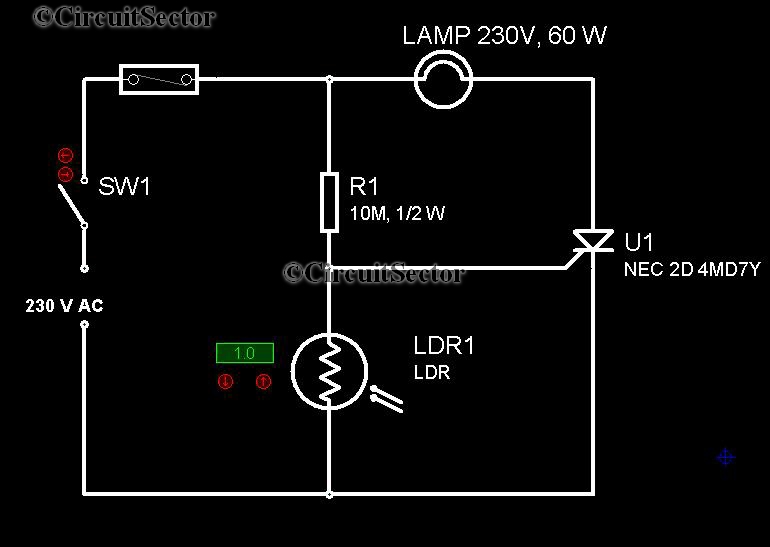
Automatic Night Lamp Circuit

Automatic Night Lamp Circuit 

It is very convenient to light a lamp in our absense in the eving when it gets dark. This automatic night lamp circuit can be used to light staircase light, porch light etc automatically using domestic powersupply. It is very in expensive in construction and we dont have to employ or depend anybody to put on the lights when we are out of station. We can connect a CFL in place of filament lamp by making necessary alterations to the circuit.


An SCR and LDR together plays the role of automation in this circuit. In figure, the resistance of LDR is low during daytime and high during night. So the required trigger pulse is developed across the SCR when it becomes dark and it is applied acrosss the gate cathod terminals and SCR is triggered and the circuit is closed.

                                                                                                         Submitted By
                                                                                                          Mohammed Hasif C                   
                                                                                                          Hasifnoor_Attasheri
                                                                                                          Thank you !
                                                                                                          God Bless You

LED Running Display Using NE555 -Submitted By Mohammed Hasif C


Here's a circuit to build a led based running display using easily available general purpose timer IC NE555 and a popular decade counter IC CD4017. This display consist of 24 LED's of four layers. The NE555 is wired as an astable multivibrator whose output triggers CD4017 counter.


On powering up the circuit, timer starts oscillates to produce triggering pulses. This pulses trigger counter IC and it counts from 0 to 5. These outputs are fed to general purpose NPN transistors BC547 which are used as current drivers for each led layer. As each of the counter output goes hih, the curresponding led layer glows sequentially. After it counts upto 6 values, resets to zero and the process repeats.

How to display custom words using this circuit.

Suppose you want to display ‘STAR.’ Build letter S with L1,T with L2, A with L3 and R with L4.When the circuit is switched on, letter S glows first. Then S and T glow sequentially,followed by S, T and A, and thenS, T, A and R. When Q4 and Q5 outputs of the counter gohigh, the completeword ‘STAR’ glows.Thereafter, letter ‘S’glows again and the cycle repeats.
                                                                                                          
                                                                                                          Submitted By
                                                                                                                              Hasifnoor_Attasheri
                                                                                                          Thank you !
                                                                                                          God Bless You