Line follower robot using 8051.
Line follower robots were one of the earliest automatic guided robots. They are able to follow a line marked on a contrasting background, usually a black line on a white surface or a white line on a black surface. Usually the line follower robot works on a closed loop feedback algorithm where the feedback from the line sensor is used by the controller for correcting the path of the robot. The sensors are usually LED/LDR, LED/Photodiode or LED/Phototransistor pairs and the controller is an electronic circuit which executes the desired feedback algorithm. Gear motors are used for driving the robotic wheels.
The line follower robot presented here is designed to follow a black line on a white background. It has a pair of sensors (LED / LDR) and works on a simple “align robot on center of the line algorithm”. Actually you does not need a microcontroller for implementing such a simple robot. A set of comparators and a motor driver circuit will happily do the job. But I am using the microcontroller just to demonstrate the technology. Also this project serves as a platform for advanced line follower robots which works on complex algorithms. AT89S52 from Atmel is the microcontroller used here.
Sensor.
The sensor part consists of a set of LED / LDR pairs for the left side and right sides. These LED / LDR pairs detect the black line on the white surface on which the robot is supposed to roam. The LDR has an inverse relationship between its resistance and the light falling on it. When a particular LED / LDR pair is above the white surface the reflected light falls on the LDR and its resistance drops, conversely when the LED / LDR pair is above the black line, its resistance rises. This variation in resistance of the LDRs are used to asses the orientation of the line follower robot in the X-Y plane. The figure shown below depicts the sensor circuit.
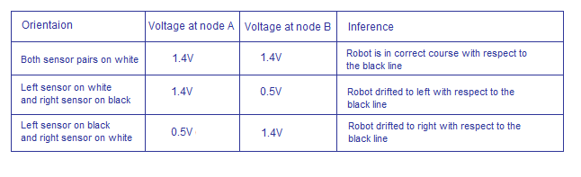
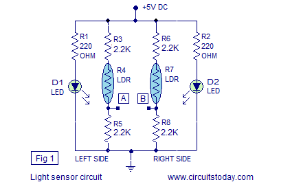 In the circuit, resistors R1 and R2 limits the current through the illuminating LEDs D1 and D2. Resistors R3, R5 and R6, R8 forms a voltage divider network together with the corresponding LDRs. The output of the sensor circuit is taken from the points labelled A and B in the circuit diagram.The table below shows the voltage at nodes A and B for the possible orientations of the sensor module.
 Comparator circuit.
The job of the comparator circuit is to convert analog voltage output of the sensor into a digital format for the microcontroller to read. The comparator circuit is built around opamp IC LM324 (IC1). LM324 is a general purpose quad opamp which can be operated from a single supply. Out of the four comparators inside LM324, only two are used here. One for the left side and the other for the right side. Circuit diagram of the comparator section is shown in the figure below.
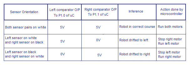
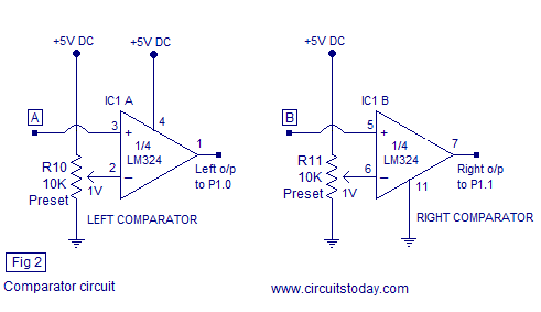 Preset resistor R10 and R11 are used to set the 1V reference for the left and right comparators respectively. Output from the left and right sensors (node A and B) are connected to the non inverting input on the left and right comparators. Output of the left comparator is connected to P1.o of the microcontroller and output of the right comparator is connected to P1.1 of the microcontroller. Both comparators are wired in non inverting mode and the table given below shows their output voltage with respect to the possible input voltage combinations.
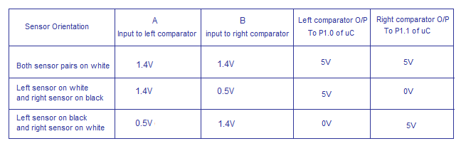
Microcontroller (AT89S52).
The task of the microcontroller here is to control the left and right motors according to the feedback signals from the left and right comparators so that the robot remains on the correct path (the black line). The logic executed by the microcontroller for keeping the robot in track is illustrated in the table below.
Motor driver circuit.
The job of the motor driver circuit is to drive the motors according to the output signals from the microcontroller. The motor driver circuit is based on ULN2003A IC. ULN2003A is a high current (500mA), high voltage (50V) darlington array consisting of seven darlington pairs with common emitter and open collector. Out of the seven channels available in the IC,only two are used here. One for the left channel and one for the right channel. Schematic of the motor driver circuit is shown in the figure below. The operation of ULN2003 is very simple to explain. When a particular input line (say pin 1) is made high the corresponding output line (pin 16 goes low) and vice versa.
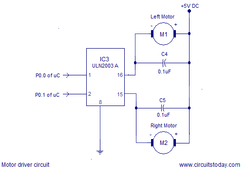 Capacitors C4 and C5 isolates the remaining parts of the circuit from the electric interference produced by the motor. The back emf voltage produced when motor is switched and the voltage spikes due to arcing of brushes mainly accounts for the above said electrical interference. These capacitors are very essential and without them you can expect sudden crashes from the microcontroller side.
Complete circuit diagram.
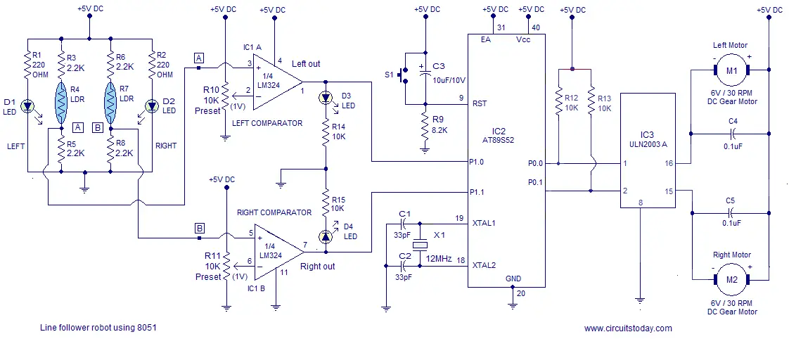
Switch S1, capacitor C3 and resistor R9 forms a debouncing reset circuit for the microcontroller. Capacitors C1, C2 and 12MHz crystal X1 are associated with the microcontroller’s clock circuit. R12 and R13 are pull-up resistors. Remaining sections of the circuit were explained already.
Program.
 ORG 000H                 // origin
 MOV P1,#00000011B        // sets port 1 as input port
 MOV P0,#00000000B        // sets port 0 as output port
 BACK: MOV P0,#00000011B  // starts both motors
       JB P1.0, LABEL1    // branches to LABEL1 if left sensor is ON
       CLR P0.0           // stops left motor
       SETB P0.1          // runs right motor
       ACALL WAIT1        // calls WAIT1 subroutine
       SJMP BACK          // jumps back to the BACK loop
LABEL1: JB P1.1, LABEL2   // branches to LABEL2 if right sensor is ON
        SETB P0.0         // runs left motor
        CLR P0.1          // stops right motor
        ACALL WAIT2       // calls WAIT2 subroutine
        SJMP BACK         // jumps back to the BACK loop
LABEL2: SJMP BACK         // jumps back to the BACK loop
WAIT1:JNB P1.0,WAIT1      // waits until robot is back from rightward deviation
      RET                 // returns from WAIT1 subroutine
WAIT2:JNB P1.1,WAIT2      // waits until robot is back from leftward deviation
      RET                 // returns from WAIT2 subroutine
END                       // end statement
About the program.
The first part of the program initializes Port 1 as input port and Port 0 as output part. After this, both motors are started so that the robot goes straight. Then the programs checks whether there is a deviation to right. If there is a deviation to right, the program stops left motor and runs right motor and waits until the robot comes back from the deviation. When the robot is back on line again, both motors are started.
If there is no deviation to right, the program checks for a deviation to left. If there is a deviation to left, left motor is stopped and right motor is activated. This condition is maintained until the robot is back on track. When the robot is back on track again, both motors are started. Lastly if there is no deviation to left or right, both motors are kept ON.
Notes.
- A 6V battery can be used for powering the circuit even though the power supply shown in the circuit diagram is 5V DC.
- For setting up the robot, place the robot on the line so that both the sensor pairs point on white and the black line goes in between them. Then adjust preset resistors R10 and R11 so that the LEDs D3 and D4 glows.
- Sensor LEDs D1 and D2 are ultra-bright green LEDs.
- OPAMP output LEDs D3 and D4 are general purpose, miniature, yellow LEDs.
- Sensor LDRs R4 and R7 are general purpose LDRs.
No comments:
Post a Comment